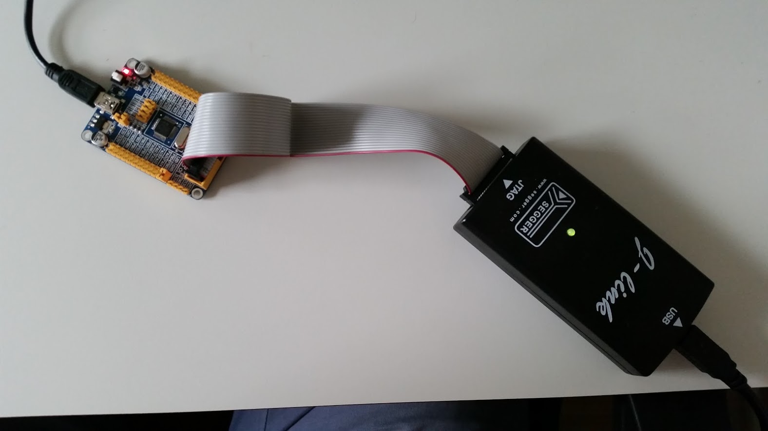
I just ordered one of those cheap 4USD STM32F103 board from ebay and a JTAG probe.
It's labeled STM32FxCxT6 Board V5.02 150118


As always, the price is as light as the documentation, but eventually digging the WWW you find interesting things.
Most electronic products available on Ebay, Aliexpress, DX, Banggood, ... are also available from Taobao and after 15mins search I found an ad selling the same looking board with a link to sample codes.
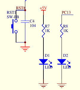
To me, the most interesting file in the archive is circuit diagram of the board.
The onboard LED is connected to the pin PC13.
Since I just want to blink an LED, I'll go for the fastest way and use the mbed online IDE.
- Add the platform NUCLEO-F103RB to your IDE.
the C8 and RB differ as follow:
R = 64 pins| C = 48 pins
B = 128KB Flash| 8 = 64 KB Flash
The memory addresses are the same. - Create a new project and use the following code
#include "mbed.h" DigitalOut led(PC_13); int main() { while(1) { led = 1; wait(0.5); // 500 ms led = 0; wait(0.5); } } - Press compile and download the .bin file.
- Assuming you know how to install openocd on your box, I like to use the following script to flash the target with the J-LINK JTAG probe.
#!/bin/sh

binpath="$1"
cfgfile="/tmp/flash_cmds.cfg"

cat > "$cfgfile" <<EOF
init
reset init
halt
flash write_image erase $binpath 0x08000000
reset run
shutdown
EOF

openocd -f /usr/share/openocd/scripts/interface/jlink.cfg -f /usr/share/openocd/scripts/target/stm32f1x.cfg -f "$cfgfile"
./flash.sh <the file from step3>
- Congrats, your on board LED should now be flashing 🙂
This isn't actually the right schematic. (I got this board too and was looking to find it!) The led is on PC13, but only if the jumper is connected. And the Boot0/Boot1 pin jumper block is completely different, there's the extra 4 pin SWD header, and the JP6 USB pullup jumper.
I got this board too. I don't have a J-Link, at least a healthy one. I have nucleo board and a clone ST-Link V2, unfortunately I couldn't write a byte of data to the flash of the chip via SWD. I both tried nucleo's SWD and ST-Link SWD(which I use for STM8). We have exactly the same board.
I bought a ST-Link V2 to try out. I'll test when I receive it and update the post (or write a new one) accordingly.
Hi, thanks for this tutorial, it works fine here (with a slightly different board from aliexpr.)
I didn't know that it's so easy to use those mbed examples with "non official" boards!
ok, the script doesn't work here... you can append new commands -c to openocd
What is the error ?
hello, I new to stm micro controllers. I have the same board stm v5.02.
Can u help me where can i get the documentation for the board and how to get started with STM
Thanks in advace