I just received my Seeeduino Arch GPRS V2. The doc is as light as the price 🙂 So don't be afraid and open the Eagle file and the bottom of the product wiki page.
You'll also need the LPC11U37 datasheet and AN_SIM900 Reference Design Guide_V1.02 (you might find an online copy of the pdf is you don't want to register yourself).
Power the SIM900
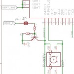
Looking at the schematic, POI1_7 is driving the PWRKEY pin of the SIM900. And from the Reference guide, we can read:
The simplest way to turn on/off SIM900 is to drive the PWRKEY to a low level for 1 second then release.
POI_2 is also used to enable the EG10 power switch. The trigger is done by changing the pin from HIGH to LOW as depicted on the schematic.
That gives you the following code:
#define PINPWR                  P1_2
#define PINONOFF                P1_7

DigitalOut eg10_pwr(PINPWR);
DigitalOut eg10_on(PINONOFF);


void EG10PowerUp(void)
{
    eg10_pwr = 1;
    eg10_on  = 1;
    wait(0.5);
    eg10_pwr = 0;
    eg10_on = 0;
    wait(1);
    eg10_on = 1;
    wait(0.5);
}
Simple GSM test
Now you can upload the following code.
It'll switch on the SIM900, send the AT command to the modem, read whatever the modem sent back and forward it on the USBSerial console.
If it works correctly, you should see the red STATUS led switching on and the green NETLIGHT led blinking.
Also, if you open a terminal emulator on your PC, you should see:
I am a virtual serial port
AT

OK
#include "mbed.h"
#include "USBSerial.h"

#define TX_GSM P1_27
#define RX_GSM P1_26

#define TX_DEBUG P1_18
#define RX_DEBUG P1_17


DigitalOut myled1(LED1); //left most LED if board is held as shown in Pinout diagram above
DigitalOut myled2(LED4); //2nd from left
DigitalOut myled3(LED3); //3rd from left
DigitalOut myled4(LED2); //4th from left (right most)


Serial gprs(TX_GSM, RX_GSM);
Timer timer;

USBSerial usb;

#define PINPWR                  P1_2 // power on EG 10, low enable
#define PINONOFF                P1_7 // switch of EG10, low enable, low for 2s to turn on EG10

DigitalOut eg10_pwr(PINPWR);
DigitalOut eg10_on(PINONOFF);


void EG10PowerUp(void)
{
    eg10_pwr = 1;
    eg10_on  = 1;
    wait(0.5);
    eg10_pwr = 0;
    eg10_on = 0;
    wait(1);
    eg10_on = 1;
    wait(0.5);
}


int wait_answer(int timeout)
{
    timer.start(); // start timer
    myled2 = 1;
    while (timer.read() < timeout) {
        if (gprs.readable()) {
            myled3 = 1;
            wait_ms(100);
            while (gprs.readable()) {
                char c = gprs.getc();
                usb.putc(c);
            }
            myled3 = 0;
        }
    }
    timer.stop(); // stop timer
    timer.reset(); // clear timer
    myled2 = 0;
    return 0;
}


int main(void)
{
    myled1 = 0;
    myled2 = 0;
    myled3 = 0;
    myled4 = 0;

    myled1 = 1;
    EG10PowerUp();
    myled1 = 0;

    gprs.baud(115200);
    while (true) {
        usb.printf("I am a virtual serial port\r\n");
        gprs.printf("AT\r\n");
        wait_answer(1 /* sec */);
    }
    return 0;
}
Nice example!
I was stuck getting serial USB comms to work for a while, thought it had something to do with the fact that it has an LPC11U37 controller, and most of the docs on mbed talk about LPC1768 or LPC11U24... But after starting the project from scratch, importing all libraries again and using your example it just worked.